AEROPublic demo

Alex BlytheAero public guided demo

Interactive demo

A CFD case, one step at a time.

Choose an example. Press Play. Let Aero guide you.

Try an example
6 steps · At your paceScripted Aero guide · Recorded results
Requirements → Math → CAD → Mesh → Solve → Render

See how Aero turns a question into a CFD workflow.

Start with the nozzle example, or choose another above.

Aero

Press Play and I’ll explain each step. You choose when to continue.

Ask Aero a question or try a change

Requirements conversation

Interactive demo guide
Aero

Describe the engineering decision you need to make. I’ll separate known inputs, assumptions, missing data, success criteria, and what must remain blocked.

This public demo uses a bounded Aero guide over curated cases. It can explain and revise the case record; it cannot start a private solver.
Inspect the full math, case data and evidence

Detailed walkthrough / Recorded evidence

Inspect each engineering stage and ask why it passed—or why it remains blocked.

The retained nozzle case below exposes the equations, geometry, mesh, solver telemetry, rendered field, and evidence gates behind the short guided experience.

AEROEngineering workbenchRECORDED RUNCOMPLETEOpenFOAM / rhoSimpleFoam

Engineering notebook

01 Problem

Evaluate steady compressible air flow through the approved converging-diverging nozzle and determine whether pressure drop is stable across the predeclared wall-refined mesh family.

02 Requirements / knowns

Use the fixed rhoSimpleFoam chain, deterministic case template, and every predeclared required gate.

Commanded mass flow
0.010 kg/sUser input
Reference pressure
101325 PaCase configuration
Reference temperature
300 KCase configuration
Unknown fields
p, U, T, rhoCase configuration

03 Assumptions

Steady, compressible perfect-gas air; one-degree axisymmetric wedge; k-omega SST turbulence model; adiabatic no-slip wall; fixed reviewed inlet turbulence quantities.

04 Governing physics

Conservation of mass
∂ρ∂t+∇·(ρu)=0
∂ρ/∂t
density accumulation; zero in the selected steady model
∇·(ρu)
net mass flux from a control volume

The evidence harness checks the solver patch-flux balance against this requirement.

Analytical
Ideal-gas reference density
ρ=pRT
p
absolute reference pressure (Pa)
R
specific gas constant for air (J/(kg K))
T
absolute reference temperature (K)

Provides a reference density for low-speed screening, not a solved density field.

Analytical
Steady mass continuity
m˙=ρAV
ṁ
mass-flow rate (kg/s)
ρ
density (kg/m³)
A
flow area (m²)
V
area-mean normal velocity (m/s)

Sets an independent inlet velocity scale from case inputs before OpenFOAM is run.

Analytical
Reference Mach number
M=VγRT
M
Mach number
γ
heat-capacity ratio
V
reference mean velocity (m/s)

Screens the expected inlet regime independently of the numerical solution.

Analytical

05 First-order analysis

Reference density 1.1768 kg/m³, inlet velocity 6.762 m/s, Mach 0.0195, and dynamic-pressure scale 26.9 Pa.

These are ANALYTICAL screening values computed before solving. Independent pressure drop is NOT YET ESTABLISHED because the inputs do not justify a fully-developed loss model.

  1. Inputs
    • Commanded mass flow: 0.010 User input
    • Reference state: 101325 Pa / 300 K Case configuration
    • Inlet area: 1.257e-3 Case configuration
  2. Equation
    m˙=ρAV
  3. Analytical estimate

    6.762 m/s

  4. Expected trend

    Increasing mass flow raises reference velocity and Mach linearly and the dynamic-pressure scale approximately quadratically.

  5. Numerical result

    NOT YET ESTABLISHED

  6. Comparison

    NOT YET ESTABLISHED

06 Geometry

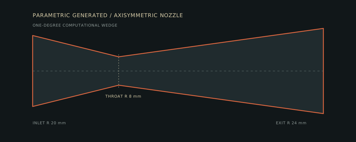
PARAMETRIC GENERATED - deterministic nozzle with 20 mm inlet radius, 8 mm throat radius, 24 mm exit radius, 45 mm converging length, and 110 mm diverging length. This is not unrestricted text-to-CAD.

07 Boundary conditions

Inlet U
flowRateInletVelocity / one-degree mass fractionCase configuration
Outlet p
101325 PaCase configuration
Inlet T
300 KCase configuration
Walls
no-slip / adiabaticCase configuration

08 Fidelity / model selection

Steady compressible k-omega SST model. Numerical acceptability and mesh independence passed, while external validation, wall-resolution suitability, and fitness for a design decision remain NOT YET ESTABLISHED.

09 Numerical method

Solver
OpenFOAM rhoSimpleFoamCase configuration
Mesher
CadQuery + Gmsh transfinite wedge, 12,600 cells at Level 4Case configuration
Execution
isolated fixed worker chainCase configuration

10 Predeclared acceptance criteria

Before execution: completion artifacts; mesh quality; residual ≤ 1×10⁻⁴; mass imbalance ≤ 1%; energy imbalance ≤ 2%; outlet-flow variation ≤ 1% over 20 samples.

Readiness additionally requires a validation reference, substantiated fidelity claims, and at least two eligible mesh levels agreeing within 2%. Missing required evidence blocks establishment.

11 Execution

The retained Level 4 run completed 4,200 outer iterations through the isolated worker. Process exit alone was not treated as engineering success; all required numerical evidence was finalized afterward.

12 Evidence

The Aero/cfd/evidence.py contract is authoritative. Residual, conservation, and monitor charts use parsed OpenFOAM telemetry only.

13 Interpretation

Numerical acceptability is PASS and the predeclared 2% pressure-drop mesh-independence gate is PASS. Overall design readiness remains NOT ESTABLISHED because validation and intended-use fidelity are not established.

Pre-solve analytical workspace

First-principles expectations from case inputs, established before OpenFOAM executes.

ANALYTICAL / PRE-RUN
CASE / NOZZLE-WALL-REFINEMENT-V6

First-order flow screening

Analytical
ṁ
0.010 kg/s
pref
101325 Pa
Tref
300 K
ri
20 mm
R
287 J/(kg K)
γ
1.4
00
Scope and authority
case inputs→analytical expectations≠solver output
\text{case inputs} \rightarrow \text{analytical expectations} \neq \text{solver output}

Every value below is established before solving from the declared reference state and inlet geometry. It is a screening calculation, not validation and not a reconstruction of CFD output.

01
Inlet reference area
Ai=πri2
A_i = \pi r_i^2

The deterministic nozzle definition supplies the 20 mm inlet radius. The full circular area is used for this independent reference-scale calculation.

Area1.2566e-3 m²
02
Reference density
ρref=prefRTref
\rho_{ref} = \frac{p_{ref}}{R T_{ref}}

Perfect-gas air at the declared reference pressure and temperature provides a pre-solve density scale. This is not the solved density field.

Reference density1.1768 kg/m³
03
Continuity velocity scale
Vi=m˙ρrefAi
V_i = \frac{\dot{m}}{\rho_{ref} A_i}

Steady mass continuity converts the commanded mass flow into an inlet mean-velocity scale using only case inputs.

Reference velocity6.762 m/s
04
Compressibility screen
aref=γRTref,Mi=Viaref
a_{ref}=\sqrt{\gamma R T_{ref}},\qquad M_i=\frac{V_i}{a_{ref}}

The reference Mach number screens the inlet regime before choosing and running the numerical model.

Reference Mach number0.01948
Reference speed of sound347.19 m/s
05
Dynamic-pressure scale
qi=12ρrefVi2
q_i = \frac{1}{2}\rho_{ref}V_i^2

This establishes an order-of-magnitude pressure scale and the expected quadratic response to mass flow. It is not a nozzle pressure-drop prediction.

Dynamic-pressure scale26.91 Pa
06
What is not established
Δpanalytical=NOT YET ESTABLISHED
\Delta p_{analytical}=\text{NOT YET ESTABLISHED}

The available inputs do not justify an independent loss model for this converging-diverging turbulent nozzle. Aero therefore does not fabricate an analytical pressure drop or reuse the CFD result as its own prediction.
Questions select the relevant structured derivation; they do not generate equations from solver output.

Engineering viewport

Axisymmetric nozzle geometry
Geometry — drag to pan, scroll to zoom
Result fields
Final engineering monitors (11)
Ux final residual
6.812e-6
Uy final residual
1.770e-5
Uz final residual
0.00318672
h final residual
2.780e-5
k final residual
8.822e-5
omega final residual
2.939e-5
p final residual
3.320e-6
inlet_total_energy_flux
-8.37146
Outlet mass flow
2.778e-5 kg/s
outlet_total_energy_flux
8.37989
pressure_drop
439.613
Solver output

Real solver telemetry

Residual convergence
Mass conservation
Energy conservation
Outlet mass-flow monitor

Aero

Aero The retained Level 4 run passed its required numerical gates, and the frozen Levels 2 / 3 / 4 family passed the predeclared 2% pressure-drop mesh-independence gate. Validation and intended-use fidelity remain not established, so this is not yet design-ready.

Explanations stay tied to structured case and evidence state. A local request can only become an allowlisted mass-flow run, fixed axisymmetric-nozzle schema, or reviewed mesh study; it cannot create commands, paths, arbitrary CAD code, solver dictionaries, or container settings.

Engineering evidence

Execution

StatusCOMPLETE
Solver runtime798.20 s
Request to result829.42 s

Numerical evidence

Numerical acceptabilityPASS

Design readiness

Overall design readinessNOT ESTABLISHED